
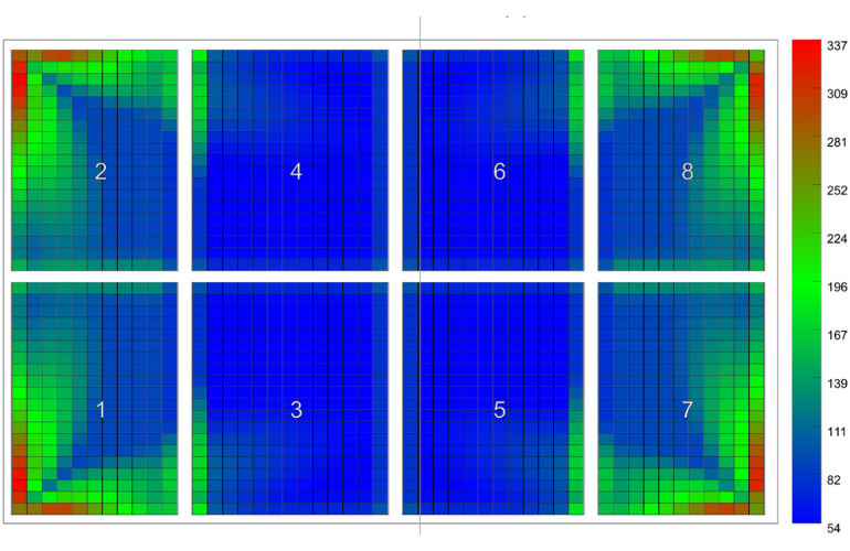

ClawFR 10 degree array
All leading suppliers of ballasted roof rack systems conduct wind tunnel testing to measure the aerodynamics of their mounting products and determine wind pressure coefficients for use in their structural design tools. To apply these coefficients to real-world scenarios, racking companies must evaluate the stiffness of their products by conducting a series of tests on entire systems built with production components and representative solar panels.
The wind load on a solar panel is calculated by multiplying the wind pressure, determined via ASCE 7 and/or wind tunnel testing, by the surface area of the structure that helps withstand the load on each module.[1]. Pressure coefficients defined in ASCE 7 or wind tunnel testing are determined in part by EWA (effective wind area, see section 26.2 of ASCE 7). As the EWAs increase, the pressure coefficients and overall wind loading decrease. For ballasted solar panels, EWAs typically rely on vertical deflection or lift and are highly dependent on the stiffness of the mounting structure.
There is currently no accepted standard methodology for measuring EWAs. Rack suppliers are therefore developing their own approaches that are mainly based on technical insight and guidance from wind tunnel experts. An array with low stiffness – read very weak connections between adjacent modules – has relatively small EWAs and usually requires much more load resistance in the form of ballast and/or roof anchors than a high stiffness array with larger EWAs.
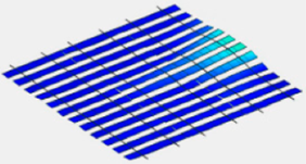
Low stiffness array |
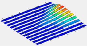
High stiffness array |
Racking suppliers are thus incentivized to overestimate the stiffness of arrays constructed with their products, as this practice reduces ballast and anchor requirements. Naturally, Exaggerated EWAs can lead to hazardous designs that are unable to withstand the worst expected wind loads at a project site and expose the system owner to property damage.
Establish EWA
The general approach to measuring EWAs involves lifting each module of an appropriately sized array while observing the displacement of surrounding modules to determine the degree of load distribution and how this helps reduce the upward forces on the module being lifted to resist. Prior to testing, the following criteria should be established: maximum acceptable lift height, how to determine whether surrounding modules are contributing, what size and shape array(s) to test, and what module size(s) to use. All these criteria influence the results in one way or another.
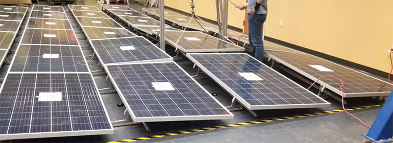
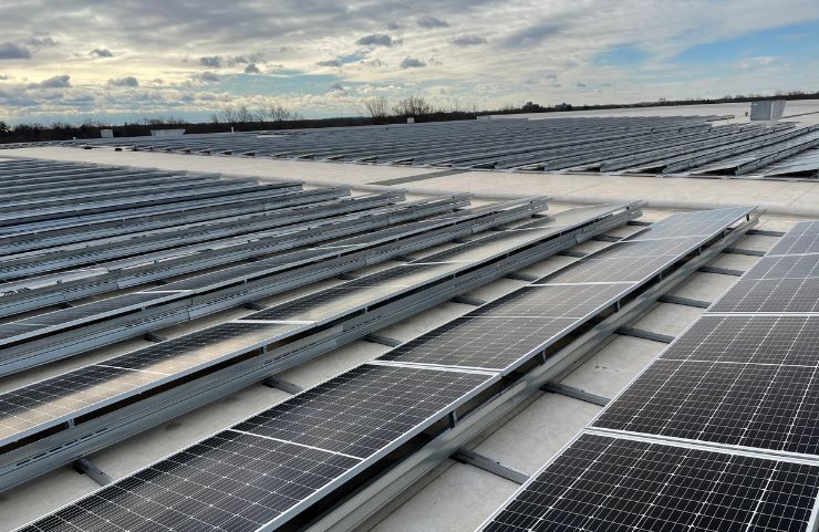
ClawFR 10 degree vertical load sharing test setup
Rack suppliers should work closely with their wind tunnel laboratory to agree acceptable aerodynamic limits for different modules in an array. Modules at the perimeter of the array may be more aerodynamically sensitive than internal modules.
When determining the acceptable lifting height, the structural behavior of the system must also be taken into account. The load used to lift a module must not cause structural failure or excessive deformation of any system component. Modules must also remain securely attached to the mounting structure after the load has been removed. Furthermore, once a section of an array is lifted, it must return to its original position after removing the lifting force. When lifting to the same height a second time, the load distribution must remain unchanged.
The module size and array configuration used in the EWA test should be representative of actual deployed systems. EWAs are typically defined in terms of a number of modules. Larger modules require stiffer structures to justify the same contribution to load distribution as modules with much smaller areas. For a given mounting platform, the EWAs for a module over 30 square meters are unlikely to match the EWAs for a 22 square meter module and therefore adjustments may be necessary as module sizes continue to grow. Likewise, the array configuration has a significant impact on the validity of the EWA. For example, it is illogical to use an EWA equal to 9 modules if an array has less than 9 modules. Attention should also be paid to the direction of the load distribution to ensure that it is applicable to a particular array.
PanelClaw’s technical team has many years of experience testing EWAs and has developed a comprehensive approach to accurately characterize its products in a way that is neither too aggressive nor too conservative. There is evidence that other companies have taken liberties in developing their approaches, sometimes resulting in grossly exaggerated EWAs.
Working with expert third parties, including wind tunnel laboratories and engineering consultancies, PanelClaw’s methodology has been scrutinized by numerous wind and building engineers with deep expertise in rooftop PV. They all concluded that the PanelClaw approach is the best of its kind. The following excerpt is from the DNV Technology Assessment of the PanelClaw ClawFR and ClawFRplus mounting systems, “DNV has reviewed the test reports for all three systems and agrees with the methodology used in determining EWAs.”
If your racking supplier has not submitted its wind design methodology, including how EWAs are determined, to an expert 3rd party for review, you should ask them to do this and review the report before using their products.
[1] Quote from the IFI wind report for PanelClaw Polar Bear 10deg Gen III HD: The ballast required to secure the solar roof mounting system depends on the stiffness of the connecting elements. Rigid members take advantage of the lack of non-simultaneous action of building- or array-induced wind gusts on large effective wind areas. If wind forces on heavily loaded zones of arrays can be largely redistributed by the interconnected substructure, the benefits of load sharing apply.
Sponsored content by PanelClaw
Comments are closed.